how does a 2 pipe water well pump work diagram Yahoo Image Search

Secretary burnt mark water pump connection diagram Wetland That Policeman
How a Well Pressure Tank Works - with Diagrams May 19, 2021 by MM Stephen Pressure tanks store and supply water to your house under pressure with the help of compressed air. When the water pressure in the tank falls below the cut-in pressure, the pressure switch activates the pump until water pressure in the tank increases to the cut-off pressure.
Beauchamp Water Treatment Blogspot Submersible Well Diagrams
How Does a Well Pump Work: Well Water Basics An introduction to well pump systems which explains the mechanics behind jet and submersible pumps as well as basic knowledge, maintenance, and troubleshooting information. Updated: December 2, 2023 / Jeremiah Zac / Well Water /
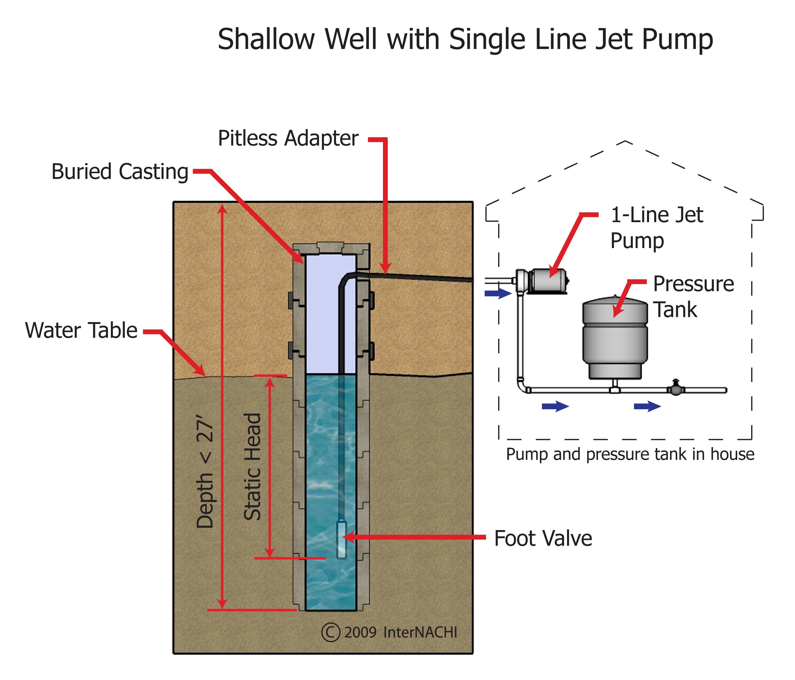
InterNACHI Inspection Graphics Library Plumbing » General » shallow
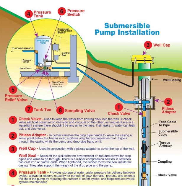
Well Pump & Pressure Tank Diagram 14 13 12 15 16 8 9 10 7 CASING 1. Check Valve Located at the top of the pump to prevent back flow into pump and hold the head of water in the system. 2. Torque Arrestor Installed directly above Submersible Pump to protect pump and well components from starting torque damage. 3. Safety Rope
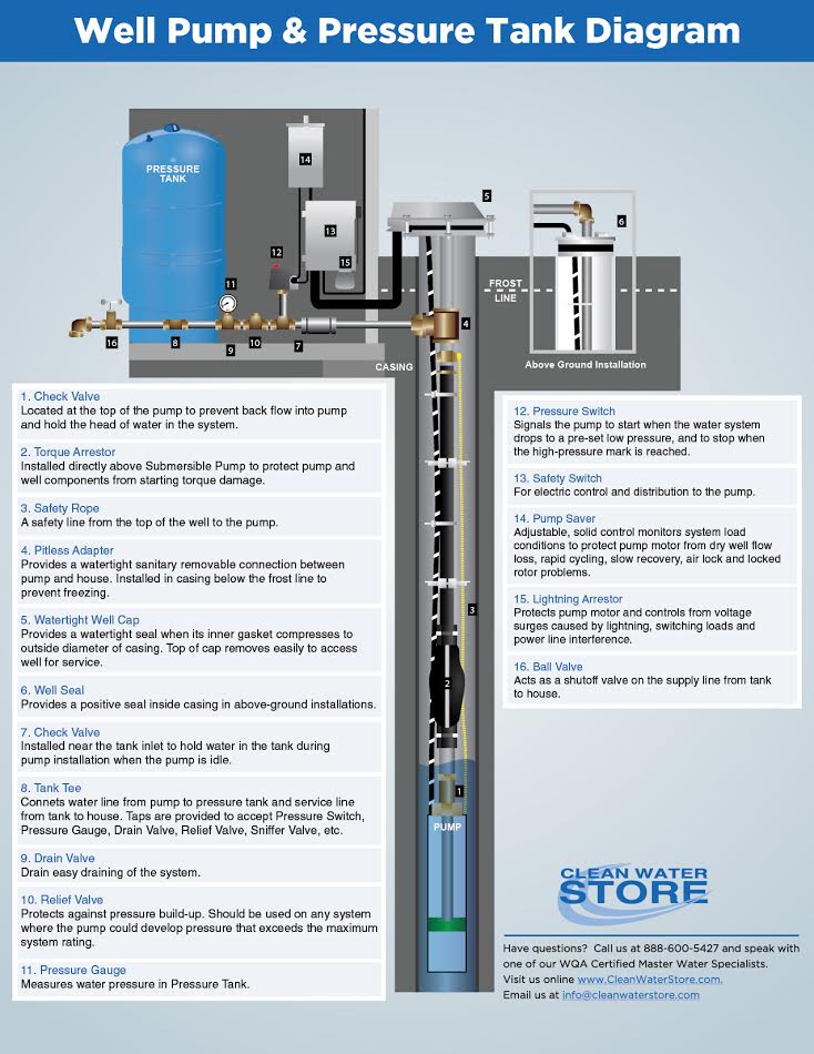
Clean Well Water Report Well Pump & Pressure Tank Diagram
How to install a Well Pump System, just a Follow Along Video of Our Day to Day jobs. Well Pump install Trench & Water line'sElectric hook up to breaker panel.
Submersiblepumpdiagram Aarohi Embedded Systems Pvt. Ltd.
6. Well Seal. Provides a positive seal inside the casing in above-ground installations. 7. Check Valve. Installed near the tank inlet to hold water in the tank during pump installation when the pump is idle. 8. Tank Tee. Connects water line from the pump to pressure tank and service line from tank to house.

House Wiring Piping Diagram Guide To Above Ground Pool Sanitizers
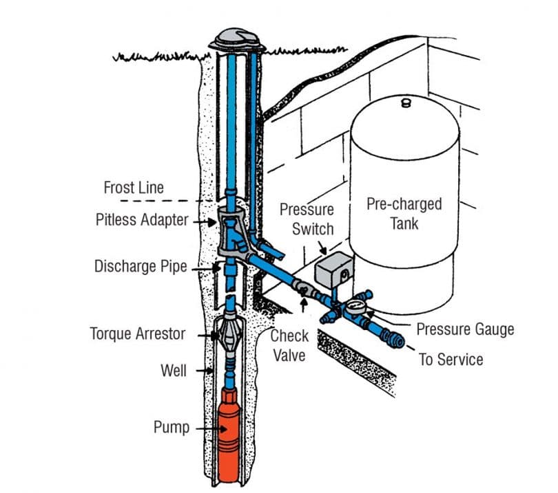
A well pump system diagram typically consists of several key components that work together to bring water up from underground wells. These components include: Well Casing: The well casing is a protective tube, usually made of steel or PVC, that is inserted into the drilled well to prevent the walls from collapsing.

Diagram Of Well Water System
An overview and description of typical residential well water system components. Pressure switch, well tank and other components explained.

10 best Well Pump House images on Pinterest Pump house, Fountain and
Pressure in the water pressure tank and in the building piping system drops. down to the well pump cut-in pressure. Typically this is 20 or 30 psi on a residential water system. The well pump pressure control switch senses the pressure drop, closes an internal electrical relay switch to turn on the well pump.

PPT Household Water Systems PowerPoint Presentation, free download
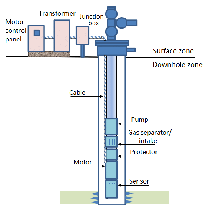
Understanding the diagram of a submersible well pump is essential for anyone involved in well maintenance, repair, or installation. The diagram of a submersible well pump typically includes important components such as the pump motor, impellers, check valve, pressure switch, and control box.
Well Pump System Diagram Wiring Diagram
How does a well work? A home water system has two important components besides the well itself - a pump and a pressure tank. Well Pumps There are many types and sizes of pumps for a home pressurized water system. Some are only designed to remove water from a source.
How To Dig A Well Getting Water for Your Family
C&J Well Company's anatomy of a water well diagram shows you how water wells work and how water gets from the ground to your home. COVID-19 RESPONSE:. One of the most important water well components, the pump, acts like a heart, pumping water throughout the system. Electric pumps draw water from inside the casing and deliver it through.

INSTALL A SUBMERSIBLE WATER PUMP Lessons for Doing It the Right Way
Intro Well Water Pressure, Pumps & Tanks - How It Works Silver Cymbal 812K subscribers Subscribe Subscribed 1.1M views 6 years ago Basic overview of a well water system and how it works with.
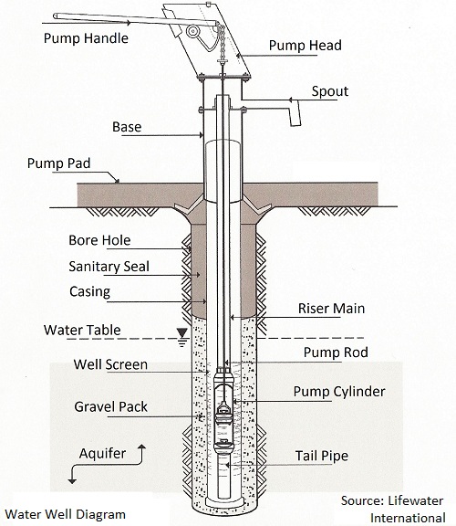
Diagram Of A Water Well Pump Illusion Sex Game
Baker Water Systems - Well Diagram Well Diagram The quality water system products described here and illustrated on the front page are some of the Baker Water Systems products used in a typical well system. (The section in the catalog where these items can be found is located in parentheses)

Submersible Water Pump Circuit Diagram Schema Digital
To keep water in the pump and plumbing system from flowing back down into the well, a 1-way check valve is installed in the feed line to the pump. Breaking the depth barrier
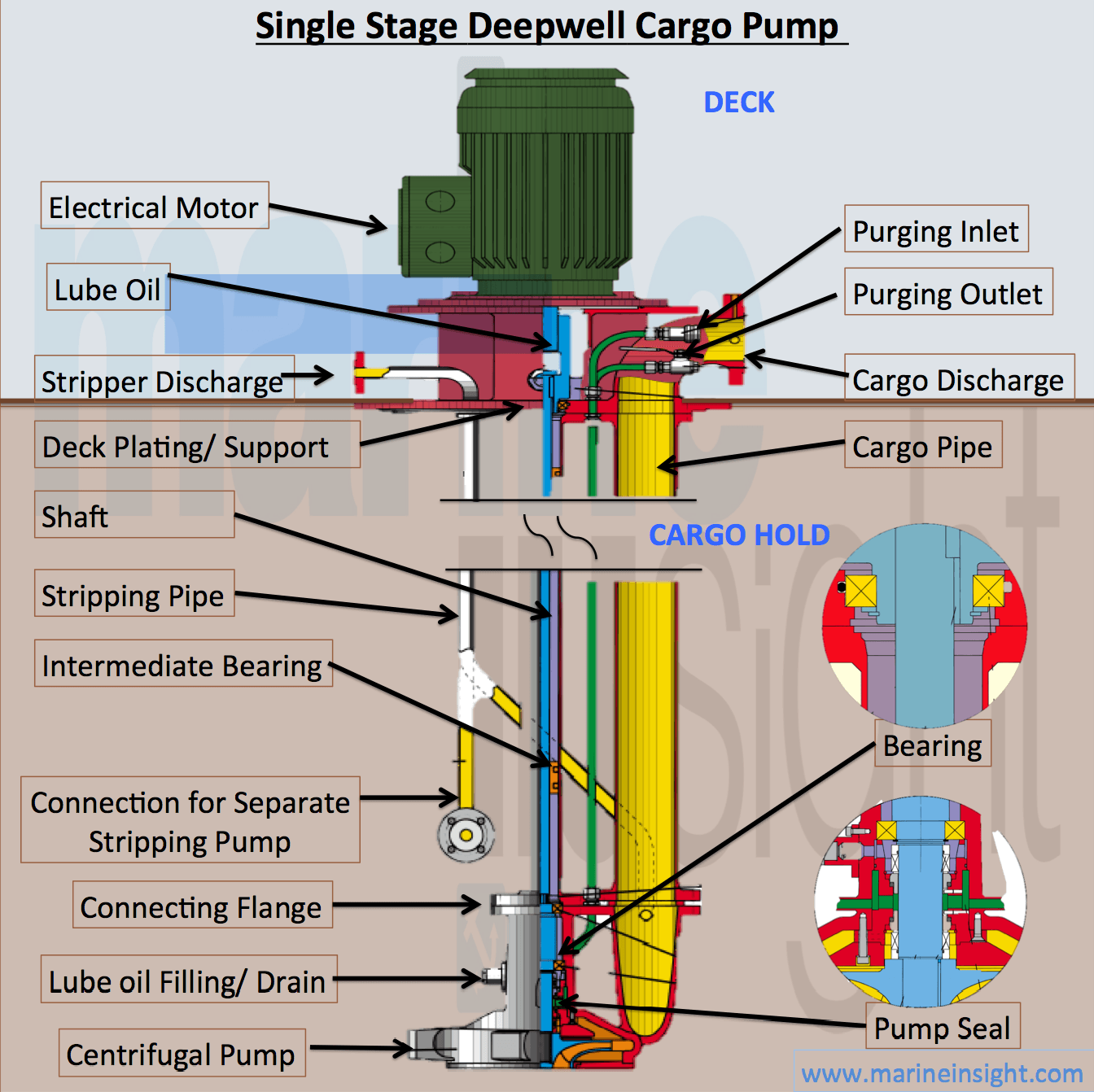
Infographics Single Stage Deepwell Cargo Pump
Home Well Water System Diagram: 22 Components Explained updated: December 9, 2023 🤝 Our content is written by humans, not AI robots. Learn More Brian Campbell - Founder, Water Treatment Specialist Considering buying a property with a well system and want to learn more about how wells work?

A Complete Guide of All Submersible Pump Components
A Dictionary of Water Pump & Water Tank Controls, Switches, & Attachments This article uses sketches and photographs to assist in locating and identifying all of the controls and switches found on residential water supply systems including the well, water pressure tank, water pump, and their associated valves and devices.
