Pam Relay Wiring Diagram Earthful
Pam Relay Wiring Diagram Earthful
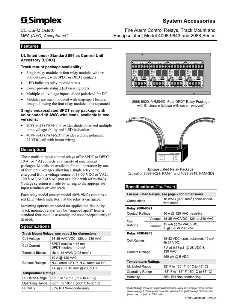
PRODUCT DESCRIPTION PAM-1 The PAM-1 Relay provides 10.0 A form "C" contacts. The relay may be energized by one of three input voltages: 24VDC, 24VAC, or 120VAC. The input voltages are polarity-sensitive and diode-protected. PAM-1 Relays contain a red LED which indicates when the relay coil is energized. PAM-2

Pam Relay Wiring Diagram
The PAM-1 Relay provides 10.0 A form "C" contacts. The relay may be energized by one of three input voltages: 24VDC, 24VAC, or 120VAC. The input voltages are polarity-sensitive and diode-protected. PAM-1 Relays contain a red LED which indicates when the relay coil is energized. The PAM-SD may be mounted by using the double-sided adhesive
[DIAGRAM] Fire Alarm Pam Relay Wiring Diagram Circuit
A Pam-1 relay, also known as a phase angle modulation relay, is a type of electrical relay used in power system protection and control applications. It is designed to accurately detect and react to changes in voltage, current, and power factor in electrical systems.

SSUPAM2 Space Age Electronics Multi Voltage Relay, PAM Series, SPDT
PAM-1 The PAM-1 Relay provides 10.0 A form "C" contacts. The relay may be energized by one of three input voltages: 24VDC, 24VAC, or 120VAC. The input voltages are polarity-sensitive and diode-protected. PAM-1 Relays contain a red LED which indicates when the relay coil is energized. PAM-2 The PAM-2 Relay provides 7.0 A form "C" contacts.

Pam Relay Wiring Diagram
PRODUCT LINE INFORMATION PAM-1 PAM-2 PAM-4 Single SPDT relay with LED, double-sided adhesive tape, mounting screw, 12" (30.48 cm) leads and six wire-nuts. Power require-ments: 0.015 Amps per position @ 24 VDC, 24 VAC, 115 VAC. Contact rating: 10.0 A @ 115 VAC, 7.0 A @ 28 VDC, 250 μA @ 5 VDC.

Ellis Circuit Pam 1 Relay Diagram
Overview The PAM-1 Relay is encapsulated multi-voltage device providing 10 Amp Form C contacts. The relay may be energized by one of three input voltages: 24 Vac, 24 Vdc, or 115 Vac. A red LED is provided which, when illuminated, indicates the relay coil is energized.

Load Wiring Pam Relay Wiring Diagram
Regardless, we use a 12/3 MC, black conductor to supply 120v to the relay module and the red conductor as a "switch leg" to provide 120v back to the elevator shunt trip breaker. I've included our typical shunt trip wiring diagram. As stated in other replies, that 120v needs to be monitored for power loss.

Pam Relay Wiring Diagram
The PAM-1 Relay is an encapulated 24VDC multi-voltage device providing 10.0 Amp form C contacts. The relay may be energized by one of three input voltages: 24 VAC, 24 VDC, or 115 VAC. A red LED is provided which, when illuminated, indicates the relay coil is energized.

Simplex Pam Relay Wiring Diagram
The wiring diagram of the Simplex PAM Relay is straightforward and easy to understand. It consists of a set of input terminals, where the alarm panel connects its output circuit, and a set of output terminals, to which the devices are connected. The relay acts as a switch, allowing or blocking the flow of electrical current to the output.

Ellis Circuit Pam 1 Relay Diagram
Description The PAM Series Relays are encapsulated multi-voltage devices with "fl ying" leads that offer versatile, reliable performance in a convenient package. Several of the versions contain a red LED which indicates when the relay coil is energized.

Pam 1 Relay Wiring Diagram
Specifications Power requirements: PAM-1: 0.015 Amps per position @ 24 VDC, 24 VAC, 115 VAC. PAM-2: 0.015 Amps per position @12 VDC or 24 VDC. PAM-4: 0.015 Amps per position @ 24 VDC or 12 VDC. Relay: UL-recognized SPDT. Contact Rating: PAM-1: 10.0 A @ 115 VAC, 7.0 A @ 28 VDC, 250uA @ 5 VDC. PAM-2: 7.0 A @ 115 VAC, 7.0 A @ 28 VDC, 250uA @ 5 VDC.
[DIAGRAM] Fire Alarm Pam Relay Wiring Diagram Circuit
PAM-1 WIRING CONFIGURATION Operating voltage 24 VDC 24 VAC 120 VAC Contact Contact rating LED display operating status Permissible ambient temperature Physical, Unit material construction color dimensions (W x H x D) Installation 15 mA, polarity protected 50 mA 30 mA (1) SPDT, dry form "C" 250 μA @ 5 VDC; 7 A @ 24 VDC;
pam 1 relay wiring diagram SyedaGustavs
The PAM-1 Relay is encapsulated multi-voltage device providing Convenient 6 in (mm) wire leads for electrical connections. age devices. The PAM-1 relay provides Amp Form-C " ( cm) deep, with 12" ( cm) wire leads @ WIRING DIAGRAMS. Encapsulated 10 amp relay. > May be energized by one of three input voltages.
[DIAGRAM] Hvac Control Wiring Diagram Relay
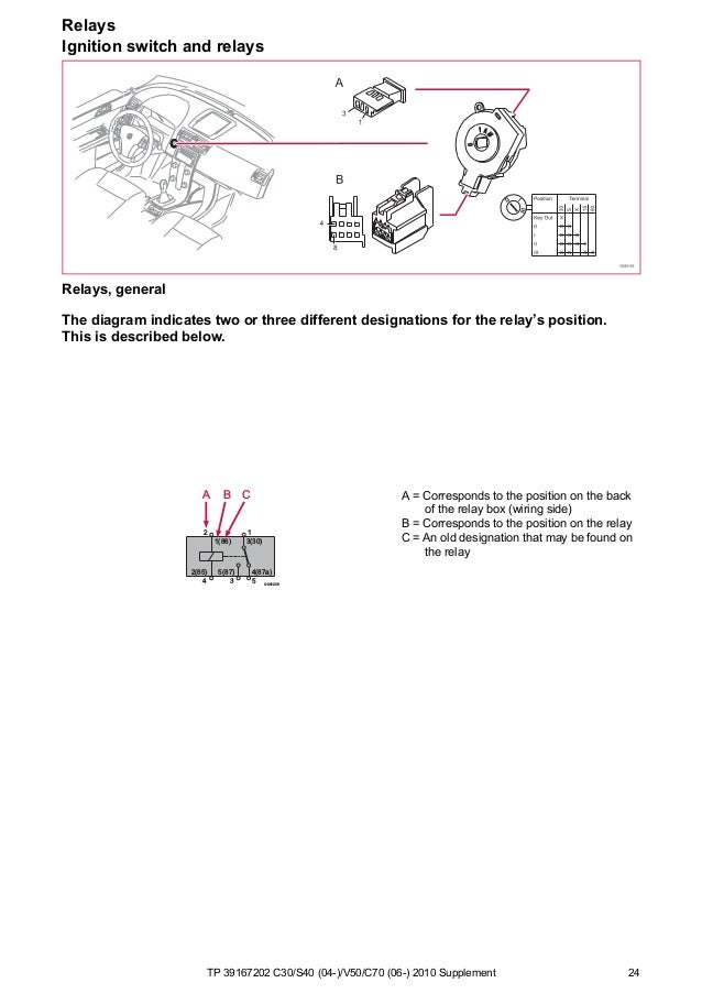
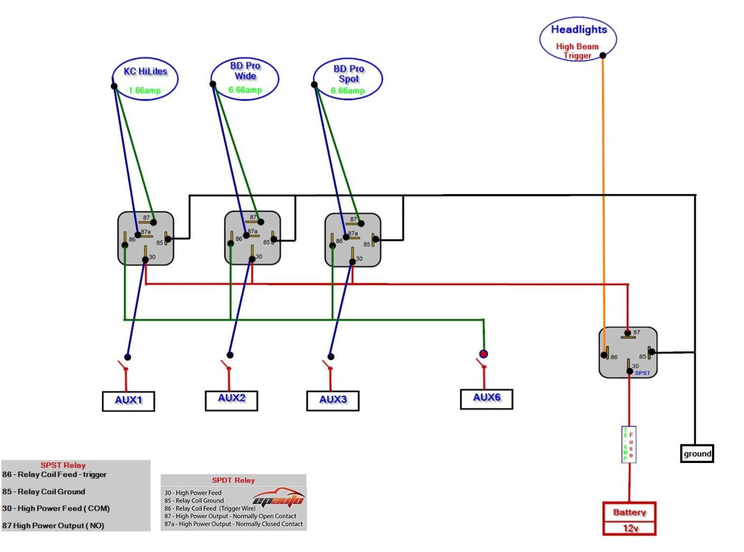
The diagram above is the 5 pin relay wiring diagram. There are different kinds of relays for different purposes. It can be used for various switching. Relay can be the best option to control electrical devices automatically. 5 pin is compromised of 3 main pins and an SPDT (single pole double throw).

Pam Relay Wiring Diagram Ella Wiring
A 12 volt relay wiring diagram is an essential tool for any electrician or automotive enthusiast. It's important to know how these diagrams work before attempting to wire up your own relay. When wiring a 12 volt relay, there are several points to keep in mind.

pam 1 relay wiring diagram SyedaGustavs
I am using an addressable fire system. I have my addressable relay connected to the slc. The other side of the relay is NC, NO, and Common. I will be using a PAM-1 relay Electrician has his 120vac in place for me. His red wire is labeled constant hot, the black is labeled "shunt trip, send 120"
