3.3. Graphical Generation of Flow Nets
[Solved] Use the provided flow nets to calculate the flow rate
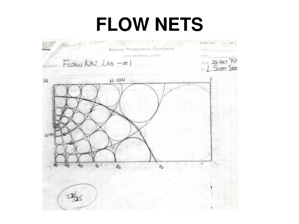
A flow net is a graphical representation of two-dimensional steady-state groundwater flow through aquifers.. Construction of a flow net is often used for solving groundwater flow problems where the geometry makes analytical solutions impractical. The method is often used in civil engineering, hydrogeology or soil mechanics as a first check for problems of flow under hydraulic structures like.
PPT FLOW NETS PowerPoint Presentation, free download ID3977795
Chapter 59 - Flow NetTo analyse the multi-dimensional flow of water inside the soil and to obtain solutions to the engineering problems such as to estimate t.
PPT Flow Nets PowerPoint Presentation, free download ID5230267
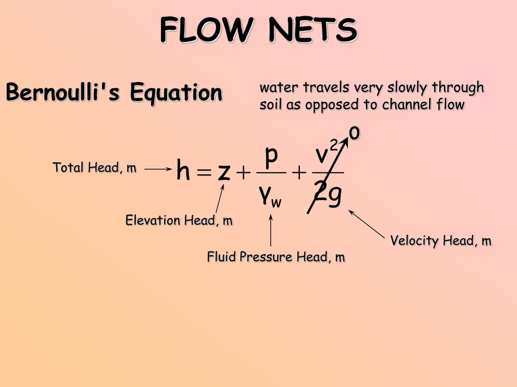
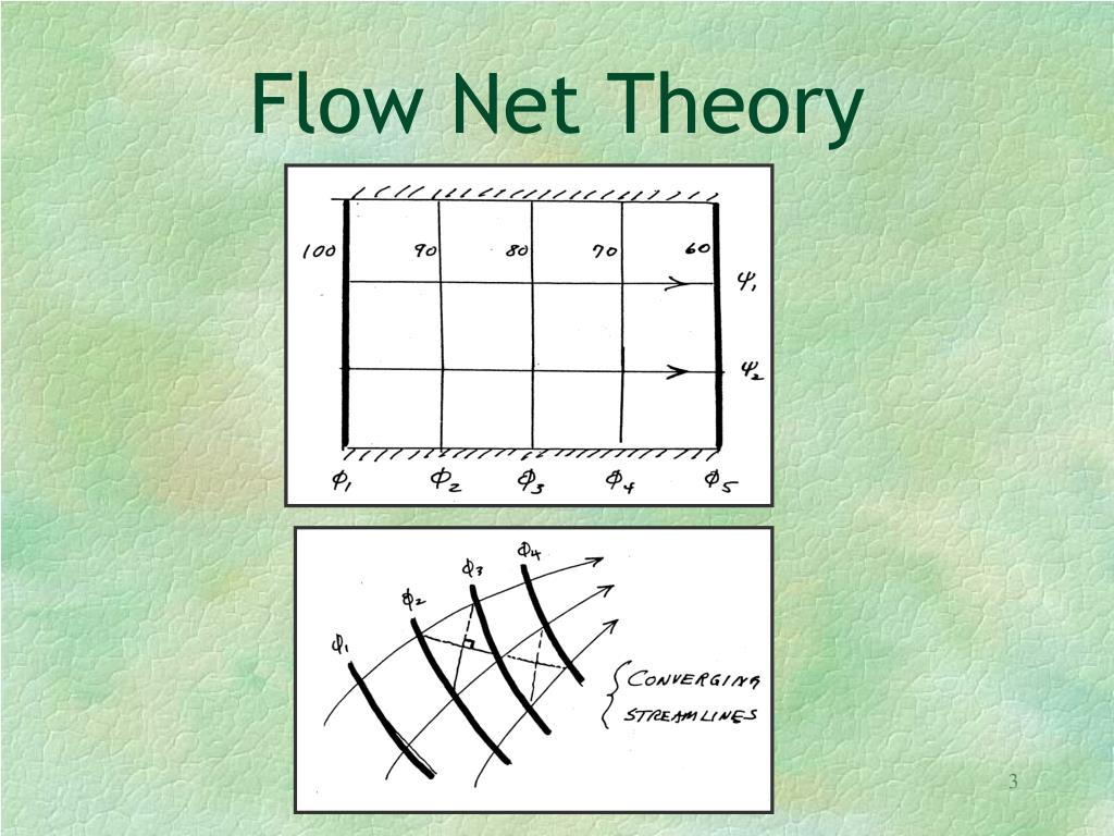
A flow net is a graphical solution to the equations of steady groundwater flow. A flow net consists of two sets of lines which must always be orthogonal (perpendicular to each other): flow lines, which show the direction of groundwater flow, and equipotentials (lines of constant head), which show the distribution of potential energy.
How To Draw Flow Nets Netwhile Spmsoalan
In this video I have discussed characteristics of Flownet and its uses under the following heads;What is Flownet in soil mechanics?The practical application.
Solved For the flow net shown below (solid lines = flow
A groundwater flow net consists of two families of intersecting lines: equipotential lines, which connect locations of equal hydraulic head, and flow lines, which show paths of groundwater flow. Together, these two sets of lines provide a visual, two-dimensional representation of the groundwater conditions under steady state (that is, neither set of lines change with […]
PPT FLOW NETS PowerPoint Presentation ID400227
If the flow net is drawn with 2 flow tubes, 9 head drops will be needed to create curvilinear squares, for a ratio of 2/9 = 0.2222. If 5 flow tubes are used then 23 head drops will produce curvilinear squares, for a ratio of 5/28 = 0.217. These small differences in the ratio of flow tubes to head drops illustrate that drawing a flow net with.
3.3. Graphical Generation of Flow Nets
A flow net is a graphical representation of the flow of groundwater through a porous medium, such as soil or rock.It consists of a network of flow lines and equipotential lines that intersect each other at right angles. Flow nets are commonly used to analyze seepage and evaluate the flow characteristics in geotechnical and hydrogeological.
PPT FLOW NETS PowerPoint Presentation, free download ID3977795
A graphically constructed flow net cannot be drawn for a heterogeneous system, so a numerical simulation of flow is used to demonstrate the impact of a lens of lower and higher hydraulic conductivity on the system of Figure 16a, as shown in Figure 17. As in Figure 16, the same volumetric flow rate enters the aquifer on the left side and exits.
PPT Flow Nets PowerPoint Presentation, free download ID5230267
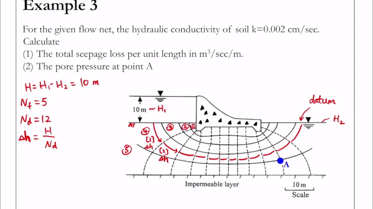
1. Discharge. The rate of flow can be determined using a flow net. The flow per unit length is obtained as, q/L = k.H. (nf/nd), where nf is the number of flow lines, nd is the number of equipotential lines, H is the total head causing flow, and k is the coefficient of permeability of the soil. 2.
PPT FLOW NETS PowerPoint Presentation, free download ID3977795
The six matchups for the wild-card round of the 2023 NFL playoffs are set, with the Cleveland Browns at the Houston Texans as the first matchup of the weekend. The San Francisco 49ers (NFC) and.
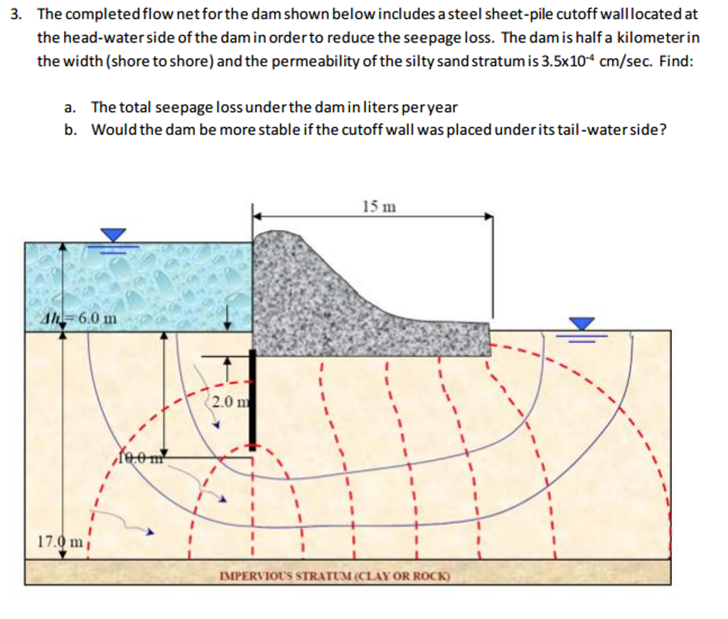
The completed flow net for the dam shown below
Denmark's Queen Margrethe II has announced her surprise abdication in a new year TV address. She will formally step down on 14 January, which will be 52 years to the day since she became queen. "I.
PPT FLOW NETS PowerPoint Presentation, free download ID3977795
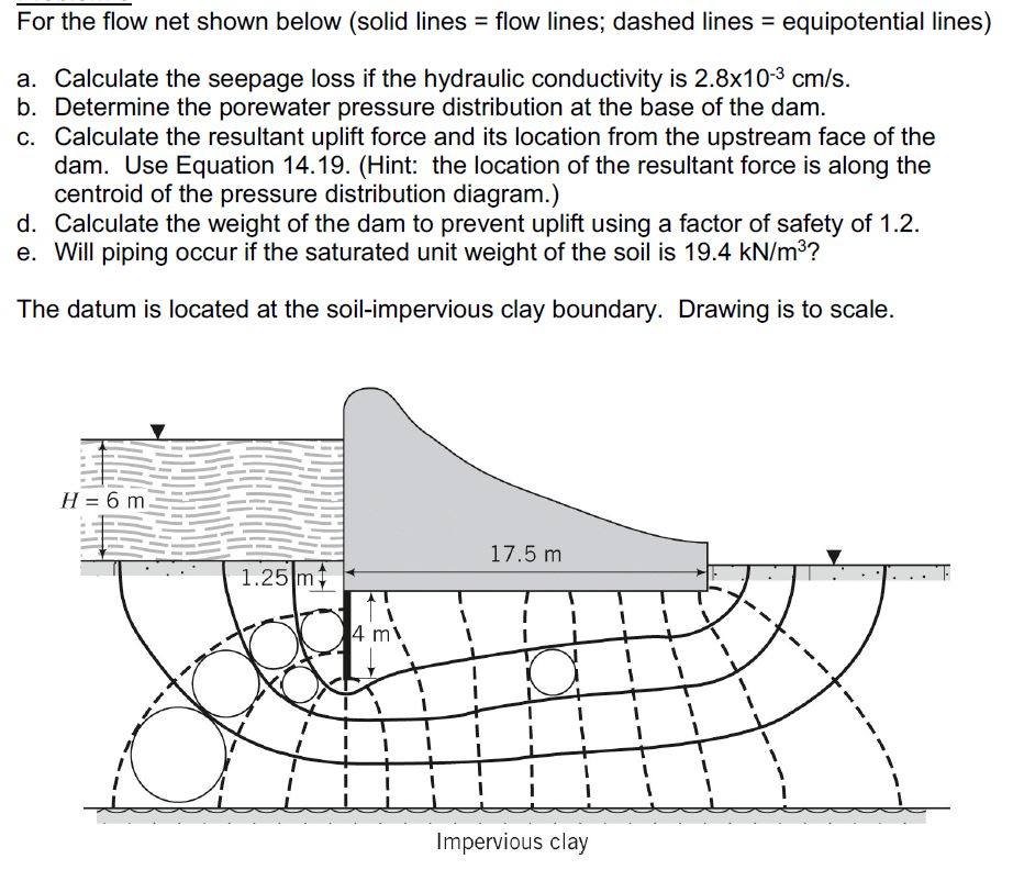
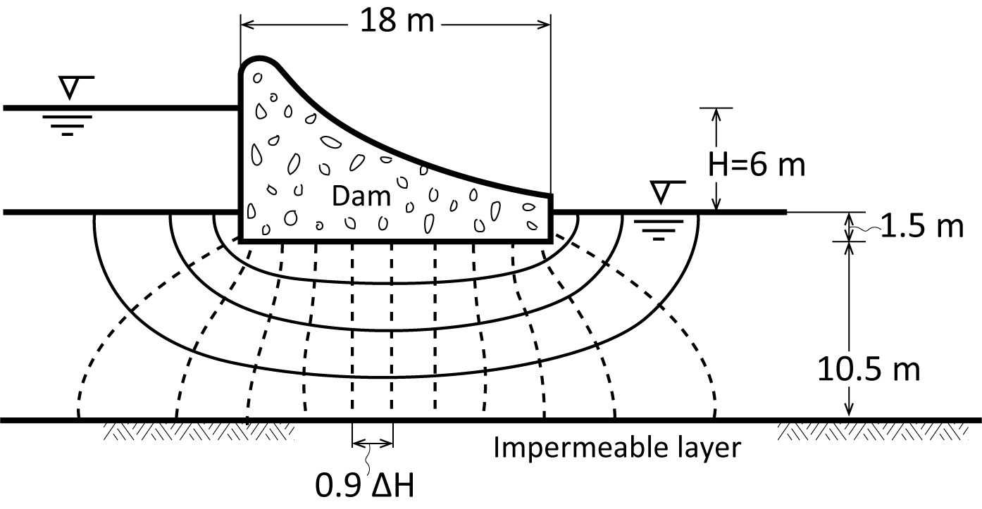
In the flow net there are 4-7 flow channels and 15 equipotential drops. The seepage is given by: q=kh 4-7 = x x = 3-1 x 10⁻⁵m3/s (per m) The pore water pressure is calculated at the points of intersection of the equipotentials with the base of the dam. The total head at each point is obtained from the flow net and the elevation head from the.
PPT FLOW NETS PowerPoint Presentation, free download ID3977795
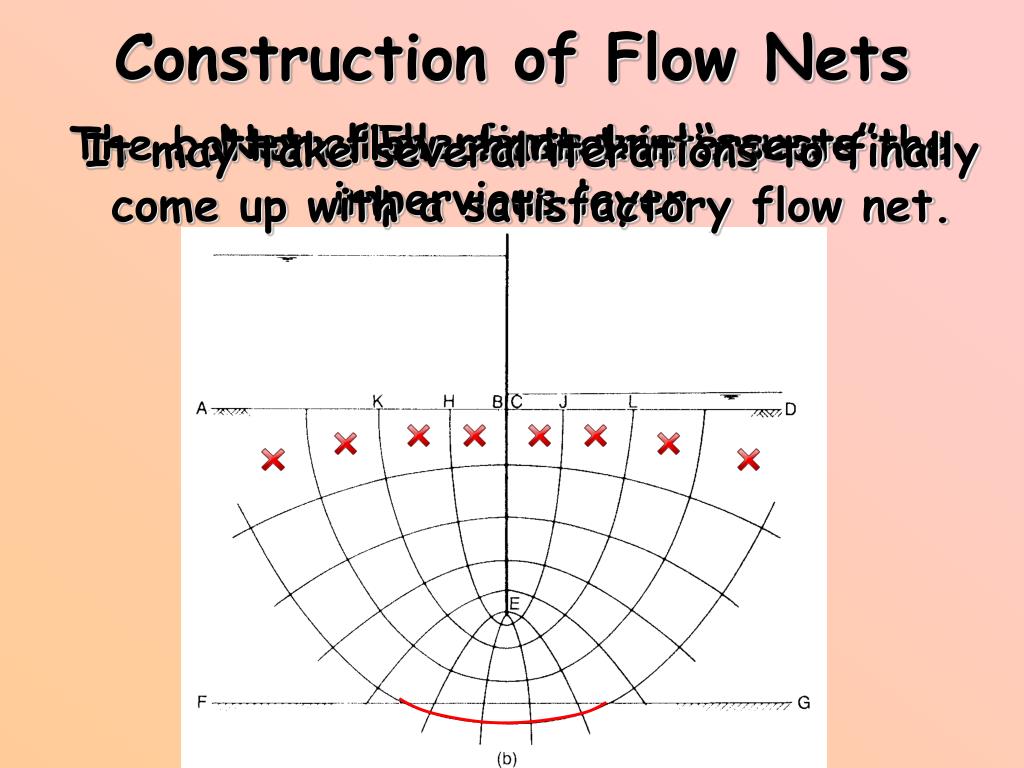
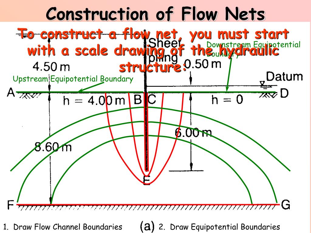
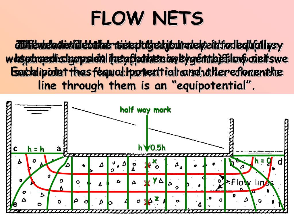
Each flow tube will represent the same discharage: Q = KiA. Procrastination is common. It is best to "dive in" and begin drawing. Just keep an eraser handy and do not hesitate to revise! Draw a very simple flow net: H. H. equipotential lines parallel constant head boundaries. flow lines parallel no-flow boundaries.
PPT FLOW NETS PowerPoint Presentation, free download ID3977795
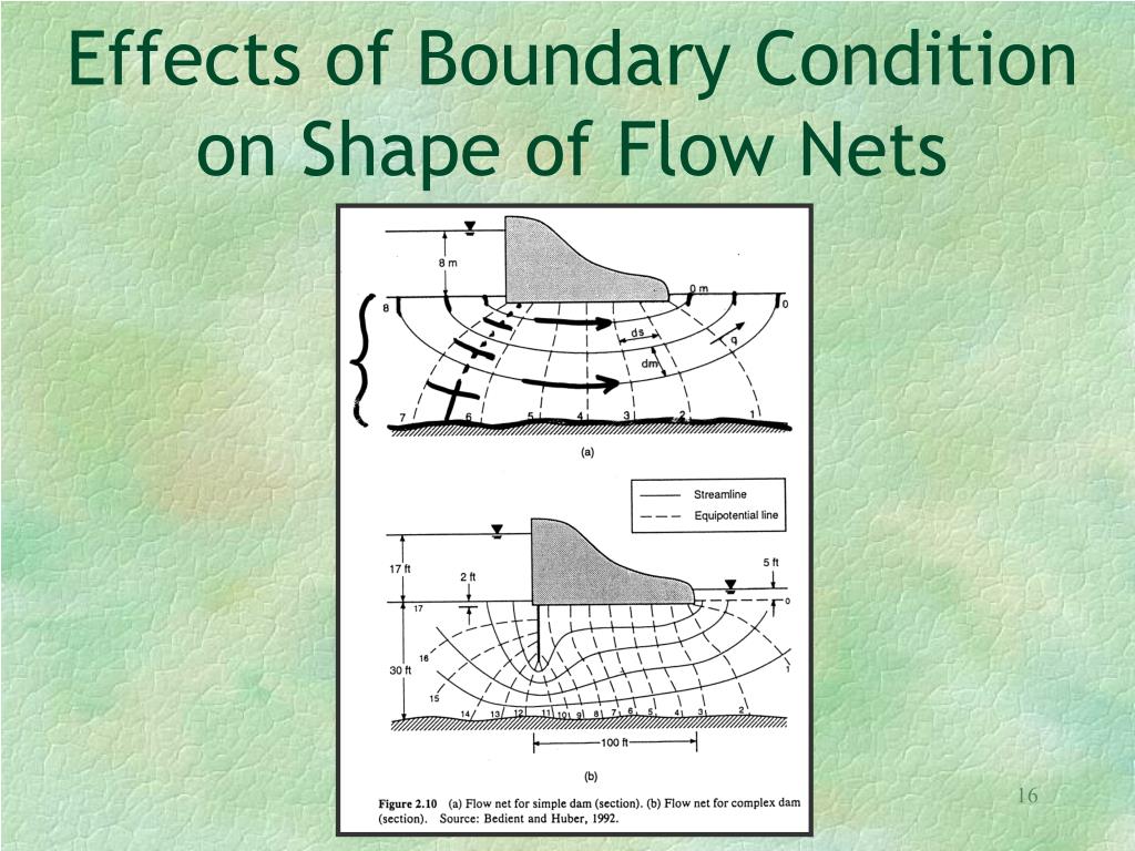
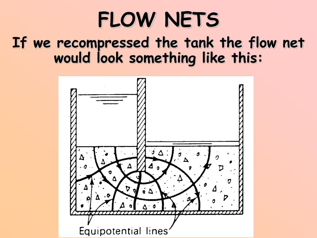
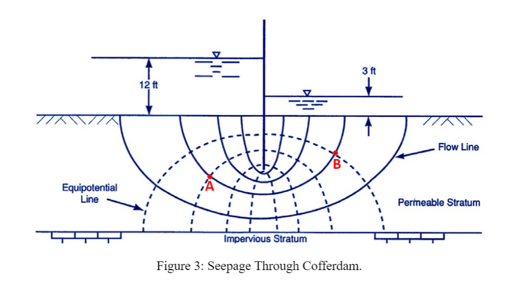
A flow net consists of two families of intersecting lines: equipotential lines, which connect locations of equal hydraulic head and flow lines that show paths of groundwater flow as shown in Figure 3. An impermeable dam is holding back a reservoir of water in Figure 3. Water seeps from the upstream reservoir into the underlying porous material.

Flow Net YouTube
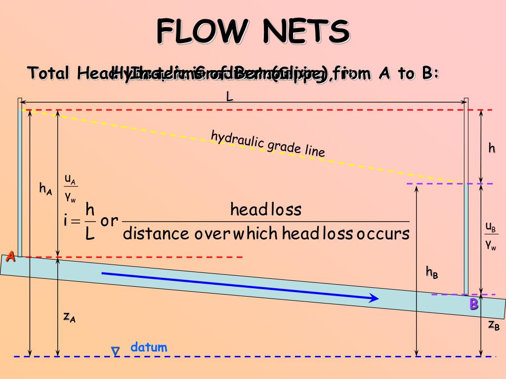
The common form of Laplace's equation for the flow of water through two-dimensional soils is: kx(∂2H/∂x2) + kz(∂2H/∂z2) = 0 ——- (1) where H is the total head and kx and kz are the hydraulic conductivities in the X and Z directions. The condition that the changes in hydraulic gradient in one direction are balanced by changes in.
Solved For the flow net depicted in Figure 3, the
The (ΑΗ) part is approximately drawn. The flow net is completed by taking into account the boundary conditions below. 1) BA (h ολ = H) is the first equipotential line. 2) ΓΘ (h ολ = 0) is the last equipotential line. 3) ΑΘ is the first flow line. 4) ΒΓ is the last flow line.
